Connecting Your Control and Cartridge Units #
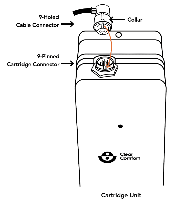
Gently align the notched outdent on the front of the Cable Connector with the keyed indent on the front of the Cartridge Connector, as shown with the arrow in Figure below. Seat the Cable Connector down onto the Cartridge Connector and turn the Cable Connector’s Collar a quarter-turn clockwise to lock the Cable and Cartridge Connector together.
If strange indicator light pattern occurs, turn OFF the Control Unit, disconnect the Cable Connector, allow 5 minutes for the ballast reset, reconnect the Cable Connector, and turn the Control Unit ON.
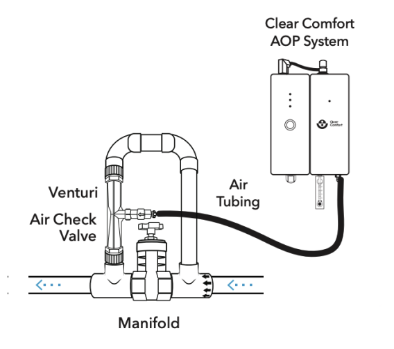
Connecting Clear Comfort AOP System to Manifold #
- Run provided 1⁄4-inch tubing from the Manifold injection port to the straight barb fitting. Length of tube should be less than 10 feet. Shorten and cut tubing as possible. See the images below.

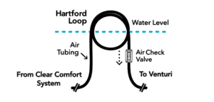
- If the Control and Cartridge Units are installed below the water line, install a Hartford loop in the 1/4-inch tubing, and wherever possible position the Hartford loop above the water line.

- Where it is not possible to position the Hartford loop above the water line, install a water check valve in the return line
downstream of the Manifold. - Measure air suction using an Air Flow Meter and set Venturi air suction to draw within the required air flow rate ranges:
- CCW100: 5 – 7 LPM
- CCW50: 3 – 5 LPM
For detailed instructions, click here.