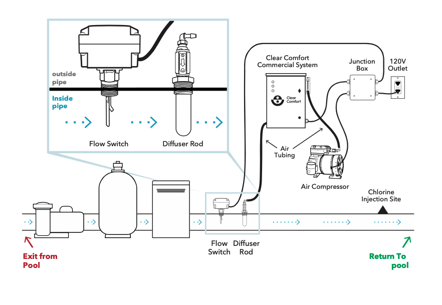
Full System Diagram: Inline Diffuser Install Kit #
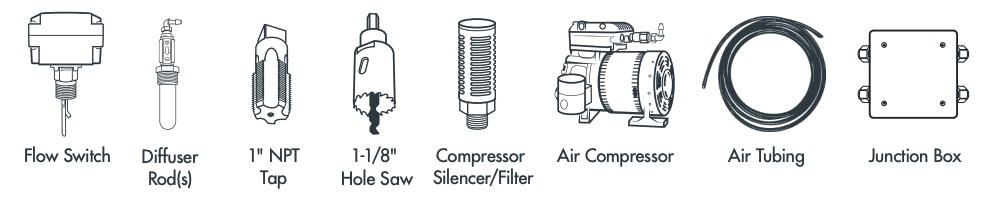
Inline Diffuser Installation Kit Contents #
 #
#
How to Install Your Clear Comfort System With a Inline Diffuser Kit #
- Turn the main pool pump OFF and switch the main pool circuit breaker OFF. Please Note: One 120VAC outlet receptacle is required to power the system.
- Locate a section of main return pipe to install the Diffuser Rod and Flow Switch. The location should be after the heater, allow the greatest distance possible from chlorine injection site, and preferably prior to the chlorine injection (see installation diagram). Diffuser must be installed after inlets to any bypass using a booster pump to avoid cavitation or loss of prime.
- (If applicable) To isolate water from pool, close the return line valves before and after the Diffuser Rod and Flow Switch install locations.
- Use included 1-1/8″ Hole Saw to drill one hole for the Diffuser Rod and one hole for the Flow Switch. Please Note: If preferred, a saddle tee with a 1″ NPT reducer bushing can be installed in place of tapping the pipe directly.
- Use the included 1″ NPT Tap to cut threads into holes for both the Diffuser Rod and the Flow Switch.
- Affix the appropriate paddle to the ow switch lever arm.
- Using the on tape or another preferred thread seal, install the Flow Switch in the hole that is first in line in the direction of flow, ensuring that the directional arrow is pointing in the direction of flow.
- Thread the check valve into the Diffuser Rod.
- Thread the assembled Diffuser Rod into the second hole in the direction of flow.
- Mount the Clear Comfort system so that there is no more than 15’ of tubing between it and the Diffuser Rod. Minimize tube length when practical.
- Mount the Air Compressor near the Clear Comfort system. Connect blue Air Tubing from the Air Compressor’s barb fitting to the bottom of the Clear Comfort system’s flowmeter (attached to the right side of the system).
- Thread the included Filter/Silencer into the open intake port on the Air Compressor.
- Insert the Clear Comfort system’s power cord into the open water tight strain relief fitting on the junction box. Connect the ground wire to the 5-lever splice connector with the other grounds. Connect the white wire to the 3-lever connector with the two other white wires. Connect the black wire to the 3-lever connector with the white and black wires.
- Secure the Junction Box cover and mount it to the wall.
- Insert the watertight strain relief fitting that is connected to the loose cord from the Junction Box into the Flow Switch and secure with conduit locknut. Connect the ground wire to the green screw ground terminal in Flow Switch. Connect the black wire to the terminal (with the red dot) and the white wire to the terminal (with the yellow dot). Important Note: Do not replace the Flow Switch cover at this time as adjustments to the sensitivity screw may be necessary.
- Connect blue Air Tubing from the bottom of the Clear Comfort system’s Cartridge(s) to the Diffuser Rod’s barb fitting, trimming the Air Tubing to the shortest length possible.
- Connect the power cord from the Junction Box to the 120V GFCI Power Outlet.
- If the system does not turn on when ow is restored, then adjust the Flow Switch sensitivity by removing its gray cover and turning the brass adjustment screw counter clockwise until the system remains on consistently.